.svg)
Plan, wire, and automate perimeter lighting with sensors and cameras to improve detection, reduce false alarms, and save energy.

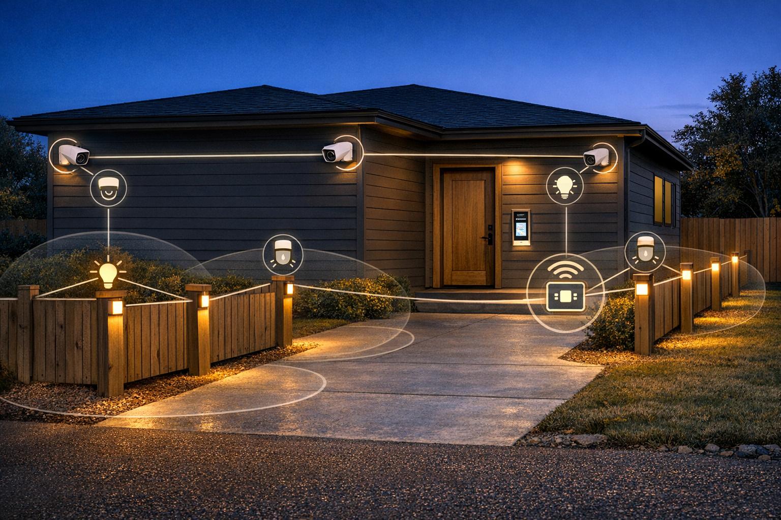
Want to improve your property’s security? Integrating perimeter lighting with your security system is a smart move. It enhances visibility, ensures better sensor performance, and creates a coordinated defense against intruders. This guide explains how to plan, install, and maintain a system that combines lighting and security for maximum protection.
By following these steps, you can create a system that deters intruders, improves camera clarity, and operates efficiently. Let’s break down each step in detail.

How to Integrate Perimeter Lighting with Security Systems: Step-by-Step Guide
Before diving into installation, it's crucial to have a well-thought-out integration plan. Skipping the step of aligning security needs with site conditions can result in systems that don’t perform as intended.
The concept here is straightforward: every detection zone should align with a matching lighting zone. This means that sensors must trigger lights specifically in their designated areas.
Start by overlaying the sensor coverage on a site map alongside your lighting layout. To avoid dark spots, ensure that adjacent light fixtures have at least 30% beam overlap. If you skip this step, cameras may lose focus or struggle to adjust their exposure when subjects move between illuminated and dark areas.
"If fixtures are spaced too far apart, the transition between 'Active' and 'Standby' states can create strobe-like effects that cause security cameras to lose focus or 'hunt' for exposure settings." - Thach Nguyen Ngoc
The type of sensor you use will influence how you define your zones. For example:
For optimal coverage, install sensors at heights between 8 and 12 feet. Mounting them too low reduces their range, while placing them too high creates blind spots directly underneath.
To improve energy efficiency, consider using "Follow-Me" sequential illumination. This approach can cut energy use by 60–70% compared to traditional static lighting systems.
Once zones are mapped out, the next step is to evaluate the physical conditions of the site that could impact system performance.
With zones defined, it's time to look at site-specific conditions to ensure the system operates reliably. Four common factors often disrupt performance:
| Site Factor | Impact | Mitigation |
|---|---|---|
| High ambient temperature | Reduces thermal contrast, blinding PIR sensors | Opt for microwave or dual-technology sensors |
| Metal fencing or gates | Causes signal bounce with microwave sensors | Reposition sensors or use PIR in these areas |
| Long cable runs | Voltage drop affects reliability | Use 48V DC low-voltage systems |
| Heavy fog or steam | Weakens PIR signals | Use microwave sensors for better detection |
Double-check that your electrical circuits and local regulations align with these requirements. For example, under NEC Article 210, a 20A breaker can only handle a continuous load of 16A (or 1,920W at 120V). Planning your circuits carefully before mounting fixtures can save time and money.
Additionally, review local rules about camera placement, fence height, and electric fence voltage. Sector-specific regulations, like CIP-014-3 for energy utilities or C-TPAT for logistics, should also be considered from the outset. Laying this groundwork ensures that the wiring and automation steps that follow will proceed smoothly.
Once you've mapped out zones and assessed site conditions, the next step is to confirm that your lighting fixtures and control systems work well together. This step is crucial to ensure that wiring and automation processes operate smoothly as part of your integrated perimeter security system. Skipping this check can lead to compatibility problems that may disrupt system performance.
Start by checking key specifications like voltage ratings, dimming interfaces, and relay types. Determine whether your system operates on low-voltage (48V DC) or line-voltage (120–277V AC). Low-voltage systems are often easier to integrate with third-party security sensors and don't require special permits for longer cable runs.
If your setup uses 0–10V dimming, you'll need dedicated twisted-pair wiring to avoid signal interference, which can cause uneven dimming. Also, ensure your control devices - such as motion sensors, photocells, or relay modules - are compatible with electronic LED drivers. This prevents issues like inrush current damage or "ghosting", where lights emit a faint glow even when turned off.
"The safest assumption is that control devices need to be verified or upgraded when converting to LED, not simply reused." - Hyperlite Technical Review
When dealing with relay logic, use NO/NC (Normally Open/Normally Closed) dry contact relays. These are compatible with nearly all alarm panels and building management systems, minimizing voltage mismatch risks. For scenarios where a single sensor controls multiple fixtures, route the signal through a contactor or relay instead of switching the load directly. This protects the sensor from potential inrush current damage.
It's also a good idea to test the supply voltage at the control terminal and simulate a trigger to check for proper voltage changes at the load terminal. If the load stays on when the sensor is idle, the line and load wires may be reversed.
After verifying your equipment, the next step is selecting the best control method for your site. Here's a breakdown of common options and their ideal use cases:
| Control Method | Use | Consideration |
|---|---|---|
| Photocells | Dusk-to-dawn automation | Place facing the northern sky; avoid fixture proximity to prevent "chattering" |
| Motion/PIR Sensors | Entry points and pathways | Ensure compatibility with LED drivers to handle inrush current |
| 0–10V Dimming | Partial-on/setback states | Requires twisted-pair wiring and consistent polarity across all drivers |
| Dry Contact Relays | Universal security bridging | Works with nearly all alarm panels and automation systems |
| Camera Analytics | Advanced threat detection | Can differentiate between humans, vehicles, and animals to reduce false alarms |
If you're using photocells, opt for models with a hysteresis circuit - a time delay of 3–10 seconds - to prevent rapid on/off cycling caused by twilight conditions or passing shadows. For lighting that needs to respond to event-driven alerts from a security platform, consult the platform's hardware compatibility list (HCL) to confirm that your fixtures and controllers are certified for API integration.
Finally, make sure lighting is positioned to enhance camera visibility rather than backlighting them. Use fill lights aimed at entry points to clearly illuminate faces, which improves identification quality in recorded footage.
Getting the wiring and power setup right is essential for the success of your combined lighting and security system. Beyond ensuring compatibility, how you wire everything directly affects safety, reliability, and how easy it will be to maintain down the road.
The first choice is deciding between low-voltage DC (commonly 12V, 24V, or 48V) and line-voltage AC (120V–240V) for your perimeter lighting. Low-voltage systems, particularly those operating at 48V DC, are often easier to install outdoors and don’t require trenching or special permits. Perion Lighting highlights this advantage:
"Operating at 48V DC, our system qualifies as low voltage, offering several important benefits for perimeter applications: Safer to install and maintain..."
On the other hand, line-voltage systems typically require more extensive work - like installing conduit, obtaining permits, and hiring certified electricians. In some cases, even new poles might be needed. This adds to both the cost and the time required for installation. For many perimeter security setups, especially retrofits, low-voltage systems are the smarter choice, cutting material and labor expenses by as much as 50% to 80%.
Once the voltage decision is made, the focus shifts to safeguarding the system and ensuring its longevity.
Protecting your wiring from electrical disturbances is critical. Outdoor circuits are vulnerable to lightning, power surges, and electrical noise. Without proper precautions, a single surge could damage lights, sensors, or alarm panels. To prevent this, install surge arrestors rated for at least 6–10kV on all outdoor circuits. Steve Shepherd of Hyperlite emphasizes this point:
"Specifying fixtures with built-in 6-10kV surge protection is a critical step in protecting your investment."
Circuit separation is another key step. Use NO/NC dry contact relays to keep your lighting and security systems electrically isolated. This prevents a power fault in one system from impacting the other, such as causing issues with the alarm panel or CCTV. Proper grounding is equally important - it reduces electrical noise that can interfere with camera image quality or trigger false motion alerts, which are common when sensitive electronics share poorly grounded infrastructure .
For outdoor wiring terminations, choose enclosures rated at least IP65 to protect against dust and water jets from any direction. When installing outdoor conduits, applying anti-seize compound to threaded fittings can protect gaskets and make maintenance easier.
Configuring your system's responses to security events is crucial for creating an effective deterrent. The right automation settings can turn a basic setup into a robust security solution.
Modern low-voltage perimeter systems often rely on an Alarm PCB (Printed Circuit Board) to link security hardware with lighting. This component processes triggers from motion sensors, cameras, or building management systems to activate the lights.
One effective approach is a standby-to-active lighting setup. Keep lights at 20% brightness for better camera exposure, then increase to 100% when triggered. This saves energy while maintaining security. For setups with "follow-me" logic - where lights sequentially illuminate to track movement - set delays between fixtures to 0.5 to 1.0 seconds for smooth tracking.
In high-risk areas, some systems include a FlashGlare mode. This feature flashes lights at intervals to disorient intruders. Additionally, enable tamper detection - if someone cuts an illumination cable, the Alarm PCB triggers a full alarm, even if the lights are off. This adds an extra layer of protection against sabotage.
After fine-tuning trigger responses, focus on sensor adjustments and fixture alignment to ensure smooth operation.
Once trigger responses are configured, it's time to address issues like false alarms and spill light by adjusting sensors and optics.
Dual-technology detectors, which combine PIR (Passive Infrared) and microwave sensing, can cut false alarms by up to 90%. While microwave sensors are better for outdoor use since they aren't affected by wind or high temperatures, they can be overly sensitive near metal surfaces like gates or fences. Lowering their sensitivity in such areas helps avoid phantom triggers. PIR sensors, on the other hand, may struggle in high ambient temperatures, making them less reliable in certain environments.
To control spill light, the key lies in the fixture design. Richard Miller of Hyperlite explains:
"A common misconception is that higher lumen output equates to better security. In practice, uncontrolled brightness creates harsh glare, which reduces the 'dynamic range' of security cameras and human eyes."
Use full cut-off (FCO) housings to focus light downward, preventing it from spilling onto neighboring properties or into camera lenses. For building perimeters, IES Type IV semicircular distributions are ideal, delivering strong illumination - typically 2.0 to 5.0 foot-candles - while keeping horizontal spill in check. When adjusting fixture angles, start at 0° tilt (parallel to the ground) and increase in 5° increments only if necessary. Over-tilting is a common mistake that causes glare and washes out camera footage.
Once your automation settings are in place, it's time to ensure everything functions as a cohesive system - not just as standalone components.
With wiring and automation configured, the next step is to test the system's overall performance:
These tests confirm that the system's triggers and responses are functioning as intended.
After verifying system performance, it's critical to document all test results for future reference. A commissioning log ensures that troubleshooting and maintenance are efficient and accurate. At a minimum, include the following for each zone:
| Parameter | Target Value | Notes |
|---|---|---|
| Photocell Turn-On Threshold | 10–30 lux | Standard for security activation |
| Photocell Turn-Off Threshold | 50–150 lux | Prevents early-morning cycling |
| System Response Latency | < 2 seconds | Ensures reliable visual verification |
| Circuit Loading | ≤ 80% capacity | NEC Article 210 requirement for continuous loads |
| Standby Dim Level | ~20% | Balances energy savings with camera visibility |
| Beam Overlap Between Fixtures | ≥ 30% | Avoids dark zones between coverage areas |
In addition to these metrics, log sensor sensitivity settings, hold times (typically 30–60 seconds for security), and zone-to-camera assignments. For instance, note that "Zone 4 triggers Camera 2 to Preset 4." Be sure to include firmware versions for any PIDS (Perimeter Intrusion Detection Systems) controllers, as updates can impact default behavior. This detailed record serves as your go-to resource for maintenance and system updates in the future.
Keeping up with regular maintenance is essential for ensuring your system stays reliable over time. Beyond basic wiring tests and automation checks, consistent inspections help address small issues - like a dirty sensor lens, a misaligned photocell, or overgrown vegetation - that can quietly undermine performance.
To keep everything running smoothly, follow this tiered maintenance schedule:
| Frequency | Key Tasks | Focus Area |
|---|---|---|
| Quarterly | Clean lenses; check seals; trim vegetation | Sensors & Fixtures |
| Semi-Annually | Walk-test motion zones; opaque cap test | Sensors |
| Annually | Verify voltage; inspect wiring; check relays | Wiring & Controls |
After completing these tasks, adjust system settings to match any new conditions on-site.
Routine maintenance does more than preserve system performance - it also calls for updates to accommodate environmental shifts.
Seasonal changes are a common reason to adjust settings. For example, winter brings earlier sunsets and reflective surfaces like snow or ice, which can bounce light back into sensors and cause rapid cycling, or "chatter". To address this, update dusk/dawn timer schedules and recalibrate lux thresholds to account for these changes. These updates work hand-in-hand with the calibration tips mentioned in the testing section.
Physical changes to the site - like a new fence, repaved lot, added structures, or updated landscaping - also require recommissioning affected zones. Confirm that sensor detection areas remain clear and functional, and verify that third-party integrations, such as camera analytics or alarm triggers, still activate the correct lighting zones. As Perion Lighting emphasizes:
"Implementing a routine inspection and maintenance plan - even just monthly - can prevent small issues from turning into serious risks."
Finally, document every setting adjustment in detail. Record the date, the specific changes made, and the reason behind them. Keeping a thorough log alongside the original commissioning records will make troubleshooting easier down the line and ensure continuity for future maintenance teams.

As discussed earlier, getting the mapping, wiring, and control systems right is crucial when integrating perimeter lighting with a security system. Luminate Lighting Group simplifies the process of choosing the right equipment, reducing the chances of troubleshooting issues down the line. Their approach builds on prior integration steps to help create a system that works efficiently and reliably.
Luminate starts by conducting thorough site assessments to craft solutions tailored to your needs. It all begins with a Design Request Form, where they gather details about your site. From this information, their experts develop photometric layouts and fixture specifications designed specifically for your perimeter. Whether you’re securing a warehouse yard, municipal facility, or another high-priority area, their designs focus on optimal fixture spacing. This often involves using multiple moderate-output fixtures placed at regular intervals to eliminate dark spots within detection zones.
When it comes to controls, Luminate ensures seamless integration of LED security lighting with third-party systems like CCTV cameras, motion sensors, and intrusion detection systems. They achieve this with Alarm PCBs, which act as communication bridges between the lighting and alarm panels. For retrofit projects, they prioritize low-voltage systems, which are not only safer but also ideal for upgrading existing setups. For perimeters with heavy camera use, they recommend fixtures with full cut-off housings to enhance target illumination.
Beyond design and integration, Luminate ensures compliance with NEC standards. They may also help you access utility rebates and 179D tax deductions, which can significantly reduce the costs of LED retrofit projects.
A thoughtfully designed perimeter lighting system not only boosts security but also improves operational efficiency. By integrating perimeter lighting with a security system, you create a setup that deters potential threats, ensures surveillance cameras function optimally, and uses energy efficiently.
As covered earlier, success lies in detailed planning and accurate execution. This includes mapping out detection zones, ensuring equipment compatibility, and handling wiring with precision. Adding smart automation and thoroughly documenting the commissioning process ties everything together, turning separate components into a cohesive, responsive system.
Using multiple moderate-output fixtures adds a layer of reliability, maintaining consistent coverage even if one fixture fails. Pairing this redundancy with tamper detection further protects your setup by instantly identifying any attempts to compromise key components.
"A well-lit perimeter isn't just a security measure - it's an investment in peace of mind." - All Security Equipment
The easiest approach to connect lighting zones with sensor zones is through integrated control systems that use zone-based automation. These systems allow lights to turn on automatically when sensors detect movement, while centralizing control to cut down on manual configuration. Additionally, low-voltage perimeter lighting can work effortlessly with motion sensors and intrusion detection systems, providing accurate zone alignment and smooth functionality.
Low-voltage systems, such as 48V DC, are a safer and more energy-efficient option. They’re also easier to install, making them a great choice for integrating with security devices like cameras or sensors. On the other hand, line-voltage systems deliver higher levels of illumination but come with more complex wiring requirements and stricter safety measures. For perimeter security, low-voltage systems are typically preferred for their simplicity and compatibility, while line-voltage works better when brighter lighting is a priority.
To cut down on false triggers while maintaining consistent visibility, pair smart lighting design with advanced detection tech. Modern lighting systems can differentiate between genuine intrusions and harmless environmental changes, reducing unnecessary alarms. Combining high-performance LED lighting with sensors helps ensure precise detection and acts as a strong visual deterrent. Strategic placement and carefully managed illumination levels eliminate glare and shadows, delivering even coverage without sacrificing security.


