.svg)
Step-by-step process for code-compliant emergency lighting: risk assessment, fixture placement, photometrics, and testing.
When power fails during an emergency, proper lighting can save lives. Emergency lighting systems are designed to ensure safe evacuation, prevent panic, and support first responders. Here's how to create an effective emergency lighting layout:
Quick Facts:
A well-designed emergency lighting system goes beyond regulations to prioritize safety during critical moments.
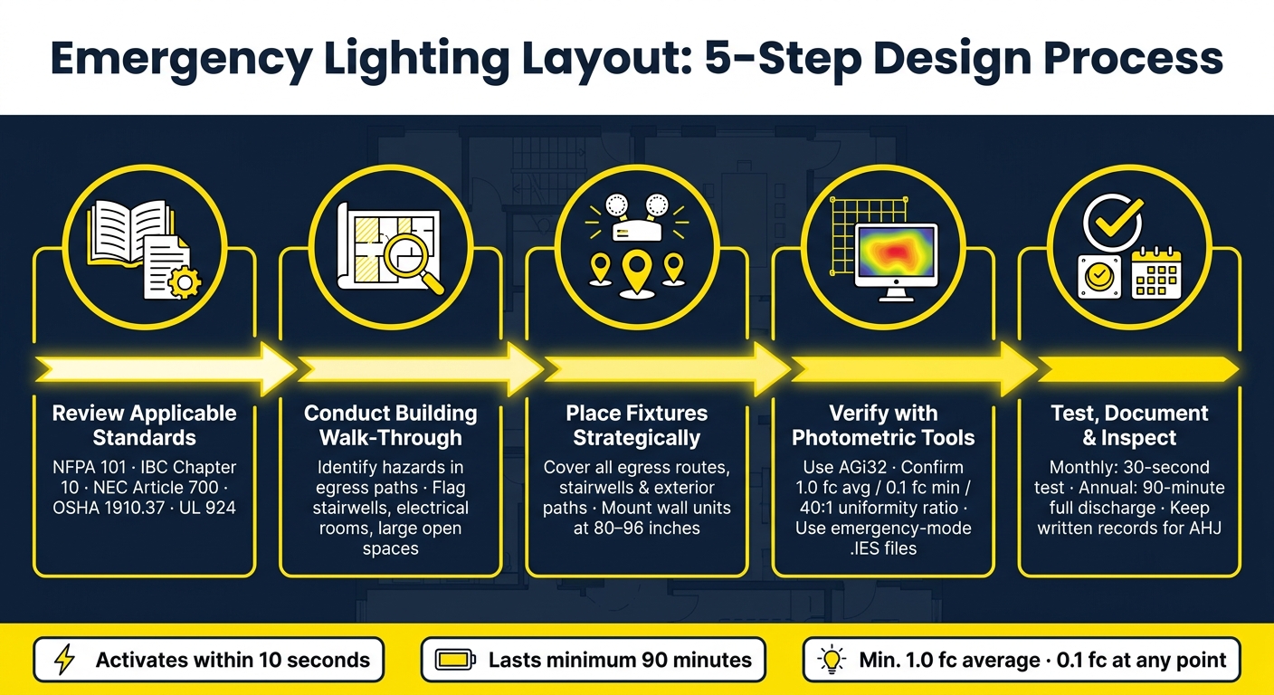
Emergency Lighting Layout: 5-Step Design Process
Before installing any emergency lighting fixtures, it's crucial to review all relevant codes. In the U.S., emergency lighting design is shaped by multiple codes that work together to ensure safety and compliance.
| Code/Standard | Primary Focus | Key Requirement |
|---|---|---|
| IBC Chapter 10 | Building design & egress | Specifies rooms that require emergency lighting |
| NFPA 101 | Life safety performance | 1 fc average, 0.1 fc minimum, 90-minute duration |
| NEC Article 700 | Electrical installation | 10-second transfer time; separate emergency wiring |
| NFPA 110/111 | Power sources | Covers generators and battery/inverter systems |
| OSHA 1910.37 | Workplace safety | Continuous exit sign illumination; clear egress paths |
| UL 924 | Equipment standards | Listing requirements for transfer switches and relays |
All emergency power and transfer equipment, including transfer switches and bypass relays, must meet UL 924 listing requirements to qualify for life safety use. This standard isn't limited to luminaires alone. While emergency lighting is exempt from power-density limits, ASHRAE 90.1 still applies to automatic controls, such as occupancy sensors.
"Where any doubt exists, it's important to clarify requirements with authorities having jurisdiction (AHJ) ahead of permit and construction to avoid embarrassment and unpleasant surprises at completion." - Tom Divine, PE, Senior Electrical Engineer
It's a smart move to consult your local AHJ early in the process. Local amendments might require higher light levels or extended durations. Additionally, the AHJ defines where the "public way" begins, which determines how far your exterior emergency lighting must extend.
Once you’ve clarified these requirements, you can move forward with assessing the specific risks in your building.
After understanding the codes, the next step is to evaluate your building for potential risks. This involves a detailed walk-through to identify hazards along all egress paths, from occupied spaces to exit discharge points. The objective is to flag areas that could become problematic during a power outage.
Pay special attention to high-risk locations, such as:
Two practical considerations can make a big difference when planning emergency lighting:
Once codes are clarified and risks are identified, the next step is determining where to place emergency lighting fixtures. The goal is straightforward: ensure every part of the evacuation path is well-lit so people can move safely and efficiently.
The focus should always be on consistent lighting along all egress paths.
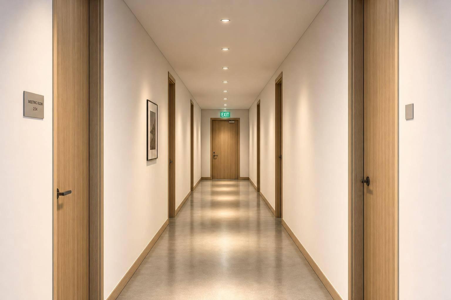
Using your risk assessment as a guide, make sure every directional change, corridor intersection, and exit door is properly illuminated. This includes all egress elements, such as occupied spaces, hallways, stairwells, and outdoor paths. Gaps in lighting can create hazards, so aim for seamless coverage. Stairwells, in particular, need special attention - each step edge must be clearly visible to prevent trips or falls. Ceiling-mounted fixtures often aren’t enough here, so consider adding wall-mounted or step-edge units where necessary.
For wall-mounted fixtures, install them at a height of 80–96 inches above the floor to ensure the light spreads effectively without causing glare. Outside the building, emergency lighting must cover the exit discharge area, including exterior landings, stairs, and vestibules, all the way to the public way. The exact distance required will depend on your Authority Having Jurisdiction (AHJ), so confirm these details early. Additionally, make sure emergency circuits are wired to stay active even if local switches turn off the normal lighting.
Just like escape routes, open areas need consistent lighting to ensure safety and visibility. Large spaces such as lobbies, assembly areas, and warehouse floors pose unique challenges because occupants may not be familiar with the layout. In these cases, uniform light distribution is just as important as brightness. Follow code requirements of an average 1 foot-candle (fc) at floor level, with no point dipping below 0.1 fc, and maintain a maximum-to-minimum uniformity ratio of 40:1.
Industrial environments bring additional challenges. Overhead cranes, ductwork, and large equipment can create shadows that undermine compliance. Fixtures with asymmetric light distribution can help fill these shadowed areas effectively. For example, Delta Wye Electric addressed this issue in a food processing plant by switching to vapor-tight LED fixtures with asymmetric optics. This change reduced emergency lighting violations by 85%, lowered the total number of fixtures by 30%, and improved overall lighting uniformity in washdown areas.
High-risk task areas - like electrical rooms, fire pump rooms, and generator rooms - require dedicated emergency lighting to allow personnel to safely operate equipment during outages. In healthcare settings, spaces used for general anesthesia or deep sedation need battery-powered luminaires that provide enough light for surgeons to safely complete or halt procedures.
Certain locations often overlooked in designs also require emergency lighting. These include fire command centers, mechanical rooms, mezzanines, and public restrooms larger than 300 square feet - a detail that frequently surprises designers.
For high-rise buildings and spaces with tall ceilings, high-output fixtures are necessary to ensure adequate lighting at floor level. Be mindful of potential LED output reductions in unconditioned spaces that can reach temperatures of up to 122°F (50°C). Areas of refuge also need proper lighting to ensure the safety of occupants and accessibility for firefighters.
The next step involves reviewing spacing and photometric layouts to confirm compliance and maintain consistent lighting coverage.
Once the fixture locations are mapped out, the next step is to ensure the spacing between them meets the required light levels at floor level. This is where photometric calculations step in, replacing educated guesses with verified compliance.
The requirements outlined in NFPA 101 and the IBC are straightforward. At the start of an emergency, egress paths must maintain an average illuminance of at least 1.0 footcandle (fc), with no single point falling below 0.1 fc. After 90 minutes of operation, these levels can drop slightly - to an average of 0.6 fc and a minimum of 0.06 fc.
| Condition | Average Illuminance | Minimum (Any Point) | Max-to-Min Uniformity |
|---|---|---|---|
| Initial (Start of Emergency) | 1.0 fc (10.8 lux) | 0.1 fc (1.08 lux) | 40:1 |
| End of 90-Minute Duration | 0.6 fc (6.48 lux) | 0.06 fc (0.648 lux) | 40:1 |
| New Stairs (NFPA 101) | N/A | 10 fc (108 lux) | N/A |
| High-Risk Spaces (Single Lamp Failure) | N/A | 0.2 fc (2.2 lux) | N/A |
Uniformity is just as critical as the illuminance levels themselves. The 40:1 uniformity ratio ensures safe evacuation conditions. Henry Baker, PE, Senior Electrical Engineer at Kohler Ronan Consulting Engineers LLC, explains:
"To provide a relatively uniform illumination at the floor, the code specifies a maximum-to-minimum illumination uniformity ratio of 40:1, meaning the brightest spot measured at the floor cannot be more than 40 times brighter than the dimmest spot."
However, aiming for a 10:1 ratio or better is often a smarter choice. The minimum code requirements allow for significant contrast, which can cause visual adaptation issues and increase the risk of tripping during evacuations.
Relying on rule-of-thumb spacing often falls short of compliance. The point-by-point method is more accurate, calculating the actual illuminance at specific floor points using the inverse square law and manufacturer photometric data. For simple corridor layouts, you can start by dividing the corridor’s length by the number of fixtures to estimate centerline spacing. However, this must still be verified to ensure no point drops below the 0.1 fc minimum.
For more intricate layouts, tools like AGi32 are invaluable. They simulate light distribution across the entire floor plan, factoring in details like room geometry, mounting heights, and surface reflectances. One critical step designers often overlook: the .ies files used in the software must represent the fixture’s output on emergency power, not its normal operating output. For battery-powered unit equipment, this output is typically 40–60% of the normal level. Using the wrong .ies file might result in a design that looks good on paper but fails in a real emergency.
To avoid issues, it’s wise to build in a safety margin. Designing slightly above the code minimums helps account for factors like AHJ interpretation differences, lamp aging, and dirt accumulation. These calculated layouts ensure a solid foundation for testing and compliance checks.
Photometric design is just one step; ensuring the installed systems function as intended requires thorough testing and verification.
Emergency lighting systems must undergo regular testing to confirm their reliability. Monthly tests should last 30 seconds, while annual tests extend to 90 minutes. These checks ensure that units activate properly, switch to battery power, and maintain the required illumination for the code-specified duration.
Steve Mesh from the Lighting Controls Association highlights the importance of this process:
"The system must be tested periodically after installation to ensure reliability. The code-required frequency of testing is once per month for 30 seconds and once annually for the full battery discharge, typically 90 minutes."
For standalone battery-powered units, testing is straightforward: press the test button on the fixture to activate its internal battery. In larger systems linked to a central inverter, testing can be initiated from a central location, such as the electrical room. During these tests, verify that UL 924 bypass relays and transfer switches override local dimming controls or wall switches, ensuring fixtures operate at full emergency output.
Generator-powered systems follow a different protocol. They require monthly load tests at a minimum of 30% of their rated capacity to ensure they reach the correct operating temperature.
Once routine tests confirm the system's reliability, proceed to a detailed final inspection to verify compliance with all requirements.
The final walkthrough relies heavily on documented testing data to confirm code compliance. A calibrated foot-candle meter is essential for measuring light levels at floor height during a simulated power outage. Emergency lighting must provide an average of 1.0 foot-candle (fc) along the egress path for the full 90-minute duration, with no point dropping below 0.06 fc and the average not falling below 0.6 fc by the end of the test.
Additionally, verify that exit signs are consistently illuminated and visible from up to 100 feet. Walk through egress paths to confirm there are no obstructions blocking sign visibility or disrupting light distribution. Emergency circuit wiring should be clearly marked - either with red conduits or labeled box covers - to prevent maintenance errors.
Tom Divine, PE, Senior Electrical Engineer at Johnston, LLC, underscores the importance of proper documentation:
"Written records of testing are required, generated manually or automatically, depending on the test method employed."
Before the Authority Having Jurisdiction (AHJ) grants final approval, coordinate directly with them to ensure your testing protocol aligns with local requirements. Pay special attention to how far exterior emergency lighting must extend to reach the "public way", as interpretations of this requirement can vary. Addressing potential discrepancies ahead of the final inspection can save significant time and effort.
Once you've confirmed your emergency lighting system meets performance standards, there are a few key points to keep in mind to ensure it remains effective.
An efficient emergency lighting layout hinges on three core principles: understanding the relevant codes, strategically placing fixtures, and testing the system under real-world conditions.
Start by familiarizing yourself with the applicable standards, such as NFPA 101, IBC, NEC Article 700, and OSHA 1910.37. Use these guidelines to map out every egress path before deciding where to install fixtures or upgrading your facility's lighting. Focus on critical areas like corridors, stairwells, direction changes, and exterior discharge zones. A common oversight is assuming illumination ends at the exit door - light must extend outside the building until occupants reach a safe public area.
Ensure light levels and uniformity meet the required standards. For example, dark concrete floors, which reflect only 10–20% of light, and overhead obstacles can create unexpected shadows or gaps. To avoid these issues, use photometric modeling before installation to predict and address any potential shortcomings.
The reliability of your system depends heavily on the equipment you choose. Select batteries that meet performance requirements and wire fixtures to operate during normal conditions. This setup ensures batteries stay charged even when the primary lights are off.
"A properly designed and maintained emergency lighting system does more than meet code - it protects your people, reduces liability, and demonstrates your commitment to workplace safety." - Delta Wye Electric
Don't forget to document your testing procedures. Keep records of monthly 30-second and annual 90-minute tests for review by the Authority Having Jurisdiction (AHJ). As Nationwide Power emphasizes, "if it isn't written down, it didn't happen."
Emergency lighting is essential in spaces like exit routes (including stairwells, corridors, ramps, and passageways), electrical rooms, fire pump rooms, generator rooms, public restrooms larger than 300 square feet, fire command centers, and rooms equipped with delayed-egress locks or sensor-release systems. The exact requirements for these areas are determined by local building codes and safety regulations.
To make sure your fixture spacing meets the required foot-candle levels, rely on photometric software to simulate the lighting layout and confirm proper illumination. This helps ensure that no part of the egress path drops below 1 footcandle (fc) during emergencies, with an absolute minimum of 0.1 fc and uniformity ratios staying within the recommended 40:1 range. Be mindful of factors like mounting heights, surface reflectance, and any obstructions. Once installed, validate everything with on-site measurements to confirm compliance.
For monthly tests, make sure to log the results of the 30-second functional test. Include details like the date, time, and any problems that come up. If you're conducting manual tests, this usually involves disconnecting the fixture from power and checking the indicator lights. However, if you have automated monitoring in place, it can handle this process for you.
For annual tests, document the results of the 90-minute test. Be sure to note the system's performance, along with the date, time, and any corrective actions taken. If you're using automated systems, these records can often be stored electronically, making it easier to keep track of everything.


